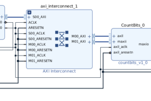
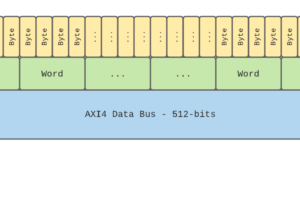
Part one and part two covered the logic of countbits, a simple VHDL module which accumulates set bits on an AXI4 bus. Part three will cover simulation to verify its functionality. I’m going to be upfront and say this is an area I’m least comfortable with. I’m new to SystemVerilog, and I can’t say I’m a fan of Xilinx’ AXI VIP (more on that later). That said, my hope is that what I’ve discovered can be of use to readers and in guiding a path through simulation of AXI Full interfaces.
Table of Contents
Block Diagram
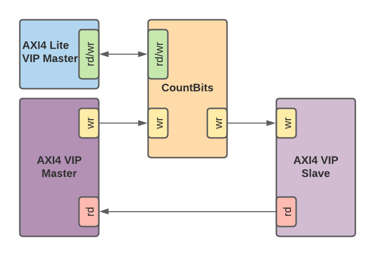
The simulation testbench can be found in cb_sim.sv. The block diagram below shows, generally, how this testbench is setup.

Note that the Countbits block is setup on the write side between the master and slave AXI4 bus, however, there’s nothing stopping a second instantiation on the read side, having another AXI4 Lite register space with a second set of accumulation registers. For the purposes of demonstration and verification, however, only a single instance is required.
Running Sim
Xilinx’ AXI4 VIP (verification IP) leaves a lot to be desired as it’s buggy, poorly documented, and not very clear in how to use. Because of a bug, you’ll need to pull the repo and first run a couple shell scripts before running behavioral simulation in Vivado:
- Clone repo
- cd CountBits/CountBits.sim/sim_1/behav/xsim/
- ./compile.sh
- ./elaborate.sh
- run behavioral sim via Vivado
Testbench
I’ll now cover cb_sim.sv in detail, but before I do I will say I’m more than a little interested in feedback on alternative AXI4 simulation tools other than AXI VIP. If you have any suggestions please contact me or post alternatives in the comment section below.
AXI VIP
A large portion of the code relates to AXI VIP, so first let’s cover that in detail. The product guide can be found here for reference.
In order to utilize VIP, importing each package is necessary. In my case, I have the primary package, axi_vip_pkg, and then the 3 specific packages for my master full (axi_vip_0), slave full (axi_vip_1), and lite master (axil_vip_0). It’s also necessary to instantiate an agent for use later.
import axi_vip_pkg::*;

import axi_vip_0_pkg::*;

import axi_vip_1_pkg::*;

import axil_vip_0_pkg::*;


axi_vip_0_mst_t axi_master_agent;

axil_vip_0_mst_t axil_master_agent;

axi_vip_1_slv_t  axi_slave_agent;
I’ll avoid discussing “xil_axi_” variables as they are commented and are too numerous to cover. I’ll also avoid covering the instantiation of the VIP blocks, as you can just use mine or what Xilinx provides when adding the VIP IP block to your design (instantiation templates and wires/logic signals are provided). Essentially I wired up “cb_top” which is my countbits module, to the AXI master, slave, and AXI Lite VIP.
There are 2 separate forked tasks, one for the AXI Full Slave, and the other for the AXI Master and AXI Lite Master. To “start” the various VIP master agents:
//Start Master VIP

axi_master_agent = new("master vip agent", axi_vip_master_dut.inst.IF);

axi_master_agent.set_agent_tag("Master VIP");

axi_master_agent.set_verbosity(400);

axi_master_agent.start_master();

//Start Lite VIP

axil_master_agent = new("axi lite master vip agent", axil_vip_master_dut.inst.IF);

axil_master_agent.set_agent_tag("AXI Lite Master VIP");

axil_master_agent.set_verbosity(400);

axil_master_agent.start_master();
One aspect to using AXI VIP I didn’t immediately understand was the requirement to have the slave respond to burst requests. Without this, the master issues a write burst and waits indefinitely for a response, with no real good indication as to why the slave isn’t responding. This was accomplished by having the AXI slave wait using get_wr_reactive() (a blocking call) and then responding with a write transaction:
task automatic axiSlave;

axi_slave_agent = new("slave vip agent", axi_vip_slave_dut.inst.IF);

axi_slave_agent.set_agent_tag("Slave VIP");

axi_slave_agent.set_verbosity(400);

axi_slave_agent.start_slave();


   forever begin

      axi_slave_agent.wr_driver.get_wr_reactive(wr_transaction);

      fill_wr_trans(wr_transaction);

      axi_slave_agent.wr_driver.send(wr_transaction);

   end

endtask
The contents of the fill_wr_trans() simply fills in the bresp with the XIL_AXI_RESP_OKAY unconditionally.
function automatic void fill_wr_trans(inout axi_transaction t);

   t.set_bresp(XIL_AXI_RESP_OKAY);

endfunction: fill_wr_trans
And now to cover what we’re really after, issuing writes and reads. Starting with AXI Lite. A simple write burst is as follows:
axil_master_agent.AXI4LITE_WRITE_BURST(4, mProtectionType, 1, mBresp);

axil_master_agent.AXI4LITE_WRITE_BURST(4, mProtectionType, 0, mBresp);
This will issue a write burst at address offset 4, which in this case is the control register for CountBits with a value of 1 (reset bit), followed by a write to the same register with 0 (clear reset).
The master write burst transaction has a bit more depth to it which will be covered below, but the command is as follows:
axi_master_agent.AXI4_WRITE_BURST(mID,mADDR,mBurstLength,mDataSize,mBurstType,mLOCK,mCacheType,mProtectionType,mRegion,mQOS,mAWUSER,mWData,mWUSER,mBresp);
The parameters for this transaction are extensive, so here’s a couple key parameters to focus on:
mADDR is the offset to start writing at (in my case, zero):
mADDR = addrOffset;
mBurstType specifies whether incrementing burst is desired, or if the same address should be bursted to:
mBurstType = XIL_AXI_BURST_TYPE_INCR;
mBurstLength specifies how many burst beats to send (0 = 1 burst, 15 = 16 bursts):
mBurstLength = 15;
mDataSize essentially specifies the number of bytes on the bus, in my case 512-bits, or 64 bytes.
mDataSize = XIL_AXI_SIZE_64BYTE;
The remaining parameters can be referenced in the guide or throughout use in my code.
Data Verification
To better control and utilize the CountBits module register space, a structure was created to wrap the data:
typedef struct packed

{

  logic [30:0] rsvd;

  bit clear_regs;

} control_reg_t;


typedef struct packed

{

  logic [63:0][31:0] byte_bits_regs;

  logic [15:0][31:0] word_bits_regs;

  logic [31:0] total_bits_reg;

  control_reg_t control_reg;

  logic [31:0] revision_reg;

} count_bit_regs_t;


typedef union packed

{

  logic[82:0][31:0] dword;

  count_bit_regs_t count_regs;

} c_regs_u;
In the current testbench, there are 2 passes made on transferring data to calculate the set bits, first with all bits set, the second is a pseudo random data set. The expected data is first pre-calculated:
for(int i = 0; i < 1024; i++) begin

  if (wr == 0) begin

    mWData[i] = 'hff;

  end else begin

    mWData[i] = $urandom_range(0, 255);

  end

  local_c_regs.count_regs.total_bits_reg += $countones(mWData);

  local_c_regs.count_regs.word_bits_regs[i/4] += $countones(mWData);

  local_c_regs.count_regs.byte_bits_regs[i] += $countones(mWData);

end
Once the burst is completed, CountBits register space is read back for verification. Notice the “raw” dword element of the union is used to simply fill in words without regard to the structure of the registers.
for(int regpos = 0; regpos < $bits(count_bit_regs_t)/32; regpos++) begin

  int data;

  axil_master_agent.AXI4LITE_READ_BURST((regpos*4), mProtectionType, c_regs.dword[regpos], mBresp);

end
Finally, total accumulation, word accumulation, and byte accumulation is verified against the known data set previously generated.
//make sure total_bits register is correct.

assert(c_regs.count_regs.total_bits_reg == local_c_regs.count_regs.total_bits_reg) else $error("Total bits count wrong!!");

local_c_regs.count_regs.total_bits_reg = 0;


//make sure word registers are correct.

for(int w = 0; w < 16; w++) begin

  assert(c_regs.count_regs.word_bits_regs[w] == local_c_regs.count_regs.word_bits_regs[w]) else $error("Word %d bits count wrong!!", w);

  local_c_regs.count_regs.word_bits_regs[w] = 0;

end


//make sure byte registers are correct.

for(int b = 0; b < 64; b++) begin

  assert(c_regs.count_regs.byte_bits_regs[b] == local_c_regs.count_regs.byte_bits_regs[b]) else $error("Byte %d bits count wrong!!", b);

  local_c_regs.count_regs.byte_bits_regs[b] = 0;

end
AXI Waveforms
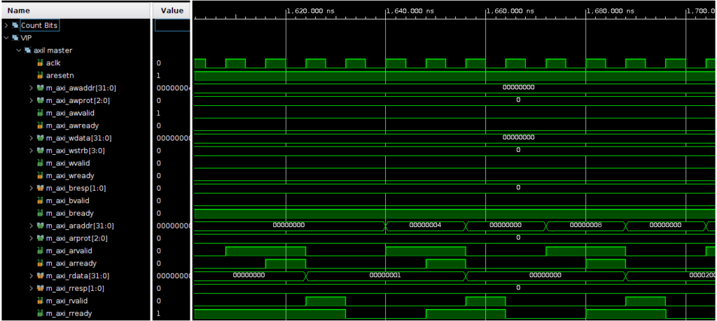
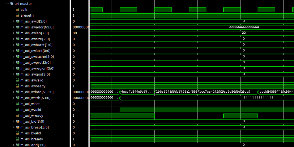
If for nothing else, having functional AXI4 waveforms handy is useful for reference with how each signal interacts with the other. Here’s the AXI4 specification for reference. Below are waveforms generated from the above testbench.
AXI Lite

AXI Full Write
Burst
The master initiates a burst by sending to the slave information about that burst.

Burst Length
An awlen value of 0xF:

Awburst
A value of 0x1 represents incrementing burst:

Awsize
A value of 0x6 is used, representing a burst of 64 bytes, or 512-bits.

Data
The data transfer follows shortly thereafter when awready goes high. The wvalid from the master indicates the data on the bus is valid. The wready pulses from the slave indicate it acquired data. The wstrb indicates which bits on the bus are valid (in this case, all of them).
AXI VIP Logging
I will say, for what it’s worth, I do like the logging that Xilinx’ VIP tool provides. Below is the AXI Full write burst of random data:
 CMD                          XIL_AXI_WRITE

   ADDR                         0x0000000000000000

   WID                          0x00000002

   LEN                          0x0f

   SIZE                         0x110

   BURST                        0x01

   CACHE                        0x0000

   LOCK                         0x00

   PROT                         0x000

   REGION                       0x0000

   QOS                          0x0000

   BRESP                        XIL_AXI_RESP_OKAY

   DRIVER_RETURN_ITEM           XIL_AXI_PAYLOAD_RETURN

   CREATION_TIME                4544 ns

   SUBMIT_TIME                  0 ns

   PAYLOAD                      1024

     BEAT[          0]          0x4ead7d544e9b6ffa5ee1e4543d8e150aa4563f33e9bfcb716d806878524b09f52e1d6e5d1dec86d10082d64cec04fab495d251386f28625d6329d612c5398751 (strb : 0b1111111111111111111111111111111111111111111111111111111111111111) :beat_delay:         0

     BEAT[          1]          0x1b3a62f3996d6f28a1f58371cc7aa42f2909cd9c509b628db9323ac3e23053f5500970ece04985632927677d205efcac0609817457f22b92b28e49c5409c48ec (strb : 0b1111111111111111111111111111111111111111111111111111111111111111) :beat_delay:         0

     BEAT[          2]          0xbdcb540587439cb8441068ceff8c507511dc7e8a7b73f787610b93f412ecf46df9a700a4f34d6d54b4b3379e99ba1d151a7c8183a0a19496dce0ef0ac5b4a7d2 (strb : 0b1111111111111111111111111111111111111111111111111111111111111111) :beat_delay:         0

     BEAT[          3]          0xa7b7731cf3cc168ac4a70668086f845b9e97e4add0ec77f1c7f836df257fbbe8d2b7233dac04c4950a1f7917faa51cf325d3fb078048f71e53b30f62f5440ef0 (strb : 0b1111111111111111111111111111111111111111111111111111111111111111) :beat_delay:         0

     BEAT[          4]          0x9a847a95815ae6050320ae7b56c65788c9e824cefd6f63fbebb56b0284ae90e931bd729b7cd37796409f24e692d8725a0c4c7338cb26e7d4804d51f7a69a8389 (strb : 0b1111111111111111111111111111111111111111111111111111111111111111) :beat_delay:         0

     BEAT[          5]          0x77f211aa8e0379cd630e31c19f6b9ca26ec525fdfdd67c71c84f818c0e2df03c41539cd1ec9ca06f67ff317d35a13eeaca903e4bd7aeab7eb990a058f51bde60 (strb : 0b1111111111111111111111111111111111111111111111111111111111111111) :beat_delay:         0

     BEAT[          6]          0x5abe2d039c1dd55722102e44fac429de16691b1caec0c3f9bb5b59b50568a00656f115ff12aef157df660ebbcf8a4924978372aaf3c5b2ed90acf8063506f58a (strb : 0b1111111111111111111111111111111111111111111111111111111111111111) :beat_delay:         0

     BEAT[          7]          0x291947dd0bf42b4c0e52b2bfe6d89a4f6cd924976cc12ad46d636d9854c767d50fa6307fb7c1a490ee6fda27d335b6c79ca5710b991156900b60b50905f6db02 (strb : 0b1111111111111111111111111111111111111111111111111111111111111111) :beat_delay:         0

     BEAT[          8]          0x6c6c44d46685359806bf9fce7e75f838412ad54634ce63fbf507e339d95c18bc2e87211d2e919a115990821d380a8e3c58788efcb116ad5cc7784e554f350e72 (strb : 0b1111111111111111111111111111111111111111111111111111111111111111) :beat_delay:         0

     BEAT[          9]          0x859867c257f2b2c341750f94b13db3adc4d2e00379e1cdc058ff36b989ce8a9f76682fe95821708c100d79cb11631345fc16b8cc66fd8d30afba3f364ed2f179 (strb : 0b1111111111111111111111111111111111111111111111111111111111111111) :beat_delay:         0

     BEAT[         10]          0xc9202e34459bdc95db9358b0c0483c2ad3107495752cb63e9b47df37916f5f64b670d82db9ef8c88b7e9a13038a3e786b1fe49b1f2e83dff0c6174f2dcdc8b1a (strb : 0b1111111111111111111111111111111111111111111111111111111111111111) :beat_delay:         0

     BEAT[         11]          0xee5a97a9c7032b4493947e827097c61024e7bc5f72df54c574dc0bad6b78bac77193f3a40627d3cd8cccd0399a07fd5332c93c47d53317ebf4082fea3f0fbb0a (strb : 0b1111111111111111111111111111111111111111111111111111111111111111) :beat_delay:         0

     BEAT[         12]          0x3d1fea60e63c92dd39aece0903e40e2faaeafbd4392434d6b1d79f63735d374e64422c25f9f5223f483703baaceb3c8e8a187e1e60240f6cb75a0ff46cb55dc3 (strb : 0b1111111111111111111111111111111111111111111111111111111111111111) :beat_delay:         0

     BEAT[         13]          0x1126b5fe77e2ad12aed3516533dac1499f77a4ea3a49a5b53d5a44850c4b71b84ef91454fd77a4f9fc9cb0037b0749f921a9ba82e6a03e9fc31a4346dd245c7c (strb : 0b1111111111111111111111111111111111111111111111111111111111111111) :beat_delay:         0

     BEAT[         14]          0x715effdeea32a59374cd3957bed85a1c0e60fda2caf91f6c9604835d631be939a168742a7a81c577eef2650393d212eb5f92f1a8737ffab61f71aebd60880862 (strb : 0b1111111111111111111111111111111111111111111111111111111111111111) :beat_delay:         0

     BEAT[         15]          0xfb812612adf987e9d32c8bc4265a5e0f06306617542da8efdc396e64516f8178e8ffe3d98782940f776144780a33caff5711ae0bdcb9514b35f5ba90835c91a5 (strb : 0b1111111111111111111111111111111111111111111111111111111111111111) :beat_delay:         0
CountBits Waveforms
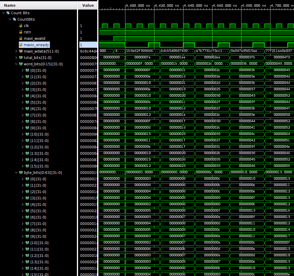
Although I don’t want to spend a ton of time on waveforms from CountBits itself, I do want to show what the accumulation registers look like, as it’s one thing to see the code, and another to watch them in action on a waveform.
Up Next…
For part four of my FPGA Series I will be going through a kernel driver which supports CountBits, and the subsequent application code to utilize that driver.

