When ramping back up my FPGA development from what was a nearly 10 year hiatus, there was quite a bit that changed, but also a lot that was familiar. In my journey through the very outer edge of Xilinx FPGA development activities (petalinux, AXI4, simulation, module drivers ,etc…) I realized I should document what I learned to hopefully aid those on the same path of learning. In what will undoubtedly be a many part series of posts, this FPGA Series will provide a detailed overview of the following FPGA related topics:
- AXI4 (Full & Lite)
- VHDL
- SystemVerilog (sim)
- Petalinux
- Linux kernel driver module
- Application code for interfacing with driver module
Table of Contents
AXI4
There’s no way I can cover AXI4 to the satisfaction of the reader so my recommendation is to follow along my code, but also reference the latest specification, specifically get a good idea of what the interface signals do and how they interact with each other. Generally there are 3 variants: AXI4 Lite, AXI4 Full, and AXI4 Stream. In this series, AXI4 Lite and AXI4 Full will be used, so don’t worry, you’ll get access to functional/practical knowledge of AXI4.
Count Bits Project
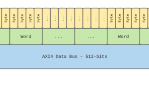
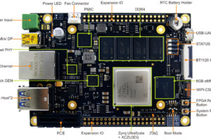
The best way to really understand concepts is to pick an arbitrary project idea and implement it from start to finish. I’ve chosen to write a piece of VHDL which will accumulate the number of bits set on an AXI4 Full data bus at the bus, word, and byte level, and make those accumulated values available to the user via an application running in Petalinux. For reference, this project will be implemented on MYiRTech’s FZ3 board which I reference in my petalinux guide. All source code is available on my CountBits GitHub Page.
AXI4 Lite
All my RTL code is written in VHDL. If you are unfamiliar with this language, I’d recommend familiarizing yourself a bit before diving into this. Let’s jump right in and start digging into my RTL which manages all the AXI4 Lite interface traffic, axiLiteCtrl.vhd.
Reviewing the interface ports, there’s the AXI4 lite interface ports (again, reference the spec if needed), and the accumulation registers shown below. I’ll cover what “register_file_typ” is later, but for now just know that there’s an accumulation register for all bits on the bus, one for each word of the bus (e.g. bits 0 to 31, 32 to 63, 64 to 95, etc…) and one for each byte (e.g. bits 0 to 7, 8 to 15, 16 to 23, etc…) that are fed into this block of RTL.
total_bits   : in std_logic_vector(AXIL_DATA_WIDTH-1 downto 0);

word_bits    : in register_file_typ(0 to (AXI_DATA_WIDTH/32)-1);

byte_bits    : in register_file_typ(0 to (AXI_DATA_WIDTH/8)-1);

reset_bits   : out std_logic
Next, the user visible register space, if you will. “register_file” is just an array of 32-bit std_logic_vectors that will hold anything we choose. It is sized to the total number of registers needed (in this case 3+num_axi_bytes+num_axi_words). I then use alias to give meaningful naming and subdivision of that register space, so there’s a revision register, control register for clearing the accumulation registers, and then the accumulation registers themselves.
signal register_file : register_file_typ(0 to LAST_REG-1);

alias revision_reg   : register_typ is register_file(0);

alias control_reg    : register_typ is register_file(1);

alias total_bits_reg : register_typ is register_file(2);

alias word_bits_reg  : register_file_typ(0 to num_axi_words-1) is register_file(3 to (3+(num_axi_words))-1);

alias byte_bits_reg  : register_file_typ(0 to num_axi_bytes-1) is register_file(3+(num_axi_words) to (3+(num_axi_words + num_axi_bytes)-1));
All the processes between line ~100 and ~190ish is just AXI4 Lite logic control to abide by the spec. This code can be generated via Vivado/Xilinx if you don’t want to write it yourself, which is where some of this originated.
The next 2 processes are worth taking a close look at, the first being the process which controls writing to the register space. To start, loc_addr is used to decode the offset into which register we’re writing to. There are 2 for loops, one for the full register space, and the other for looping over each byte within the 32-bit bus. There’s a check to ensure the accumulation registers aren’t written (addr_index < 2). This loop structure is a generic structure that allows any number of registers and combinations to be supported from one RTL block to the next.
  ----------------------------------------------------------------------------------

  ----------------------------------------------------------------------------------

  slv_reg_wren <= axi_wready and axil_wvalid and axi_awready and axil_awvalid;

  process (axil_aclk)

    variable loc_addr : std_logic_vector(opt_mem_addr_bits downto 0);

  begin

    if rising_edge(axil_aclk) then

      if axil_aresetn = '0' then

        register_file <= (others => (others => '0'));

      else

        loc_addr := axi_awaddr(addr_lsb+opt_mem_addr_bits downto addr_lsb);


        revision_reg   <= REVISION;

        total_bits_reg <= total_bits;

        word_bits_reg  <= word_bits;

        byte_bits_reg  <= byte_bits;

        --------------------------------------------------------------

        if (slv_reg_wren = '1') then

          for addr_index in 0 to (LAST_REG-1) loop

            for byte_index in 0 to 3 loop --# bytes per data bus

              if loc_addr = std_logic_vector(to_unsigned(addr_index, loc_addr'length)) then

                if (axil_wstrb(byte_index) = '1') then

                  if addr_index < 2 then --everything beyond this is read only

                   register_file(addr_index)(byte_index*8+7 downto byte_index*8) <= axil_wdata(byte_index*8+7 downto byte_index*8);

                  end if;

                end if;

              end if;

            end loop;

          end loop;

        end if;

      end if;

    end if;

  end process;

  ----------------------------------------------------------------------------------
Lastly, and very similarly, a process is used to manage reading the register space, looping over all addresses in the register space, assigning the appropriate 32-bit register value to reg_data_out (thus axi_rdata).
slv_reg_rden <= axi_arready and axil_arvalid and (not axi_rvalid);

  ----------------------------------------------------------------------------------

  process (axil_aclk)

    variable loc_addr : std_logic_vector(opt_mem_addr_bits downto 0);

  begin

    if rising_edge(axil_aclk) then

      if axil_aresetn = '0' then

        reg_data_out <= (others => '0');

      else

        -- address decoding for reading registers

        loc_addr := axi_araddr(addr_lsb+opt_mem_addr_bits downto addr_lsb);

        for addr_index in 0 to (LAST_REG-1) loop

          if loc_addr = std_logic_vector(to_unsigned(addr_index, loc_addr'length)) then

            reg_data_out <= register_file(addr_index);

          end if;

        end loop;

      end if;

    end if;

  end process;


  axi_rdata <= reg_data_out;

  ----------------------------------------------------------------------------------
These are the core elements of what is needed to support register access via an AXI4 Lite interface.
VHDL Package
Previously I mentioned “register_file_typ”. This type is defined in a custom package, cb_pkg.vhd. As a reader it’s worth taking a look at the structure of this package, as they are very helpful in providing generic functions and types which can be used throughout your VHDL. Back to the register_file_typ, which is an array of a subtype called register_typ. Register_typ is simply a std_logic_vector of the width which the axi4 lite registers are, in this case, 32-bits.
  subtype register_typ is std_logic_vector(31 downto 0);

  type register_file_typ is array(natural range <>) of register_typ;
Up Next…
Next I will go over the core logic of what makes countbits work (what fills in those accumulation registers), and the simulation environment used to validate its functionality.


