I’ve recently found myself taking interest in FPGAs again. For the first 7-8 years out of college, I worked with FPGAs on and off, mostly Altera Cyclone parts, but also Xilinx toward the end. I then transitioned into writing firmware (C/C++) and haven’t worked with them since, until now. I decided to purchase an FZ3 Card from MYiRtech. I liked the fact that it had a Zynq UltraScale+ part at a relatively affordable price. This development board doesn’t have native Vivado support yet (not available in board selection when creating a project), however, MYiRtech provides project files which got me started for both Vivado development as well as petalinux. There is no real application I had in mind when purchasing this board. It’s really something I’m using as a test vehicle where I can learn Xilinx tools, petalinux, and refresh my VHDL knowledge. I’m going to create a series of posts which should hopefully help in getting people started on learning the previously mentioned technologies, but first I will begin by providing an overview of my development board and setup.
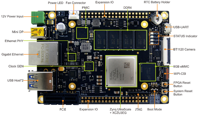
Table of Contents
Peripherals
As I said before, I purchased this primarily to learn Xilinx tools with a focus on the Zynq UltraScale+ line, so peripherals weren’t a top priority, however, there are a few that are important to me. Gigabit Ethernet was basically a requirement, with the exception that I *may* have been ok with wireless if available. JTAG so I can download code to the board and debug if needed. For this I ended up picking up a used Xilinx Platform Cable USB II from ebay which has been working great so far. DRAM and QSPI Flash typically comes standard, other than that, I didn’t really have an application in mind that would require any particular peripherals.
Bench Setup
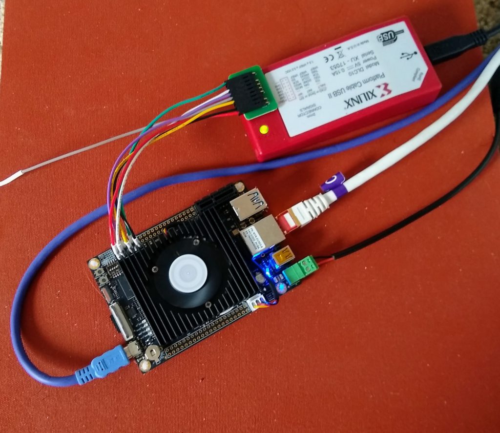
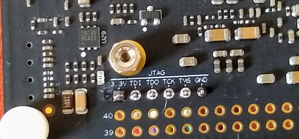
My setup is generally what you’d expect. I have 2 USB cables, one for UART (blue) and one for the platform cable (jtag), an ethernet cable (white) which I direct attach to my computer for petalinux ssh (we’ll get to that later), and the power cable to the FZ3. I will say, one of my issues with this board is its power cable. When it is connected and working it’s great, but when I pulled it out of the box, the black wire slipped out of the connector, so I had to re-attach and tighten down to keep it from slipping back out. One thing I did think was nice on this board was the silkscreen labeling of the jtag pins, so I didn’t have to get a manual out to figure out how to connect my platform cable.
Tools Setup
The computer I have connected to the FZ3 card is natively running Ubuntu 20.04, however, that’s technically “not supported” by the Vivado version I’m using so I run a VirtualBox of Ubuntu 18.04 to ensure I don’t have any issues. The full list of tools I’m using is below.
- Ubuntu 18.04 LTS (VirtualBox)
- Vivado 2019.1
- Petalinux 2019.1
Support Files
MYiRtech provided support files in the form of a zip file download. To save some time, below is the tree output of what they provided to give you an idea. I believe their link is public for these files and can be found here.
user@computer$ tree -d -L 3
├── 01-Document
│   ├── Datasheet
│   │   ├── CPU
│   │   └── Peripheral
│   ├── HardwareFiles
│   │   ├── BTB
│   │   ├── Dimension
│   │   ├── Libs
│   │   ├── PIN_MAP_RouteLength
│   │   └── Schematic
│   ├── Pictures
│   └── UserManual
│   ├── Chinese
│   └── English
├── 02-Images
│   ├── Linux-Images
│   │   ├── 2GB_DDR
│   │   └── 4GB_DDR
│   └── Petalinux-Images
│   ├── 2GB_DDR
│   └── 4GB_DDR
├── 03-Tools
│   └── Seriel Driver
├── 04-Linux_Source
│   ├── Bootloader
│   │   ├── 2GB_DDR
│   │   └── 4GB_DDR
│   ├── Examples
│   │   ├── camera
│   │   ├── can
│   │   ├── leds
│   │   └── network
│   ├── Filesystem
│   ├── Kernel
│   ├── Petalinux
│   │   ├── 2GB_DDR
│   │   └── 4GB_DDR
│   └── Toolchain
└── 05-ProgrammableLogic_Source
├── 2GB_DDR
└── 4GB_DDR
└── EdgeBoard_ZU3
I went right to the Vivado project and found that they had a rather extensive sample project which seems to generate some sort of video output pattern.
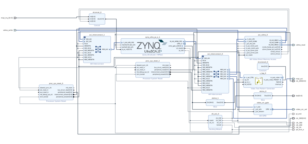
Oddly enough, it doesn’t even build if you don’t have licensing, which I found a bit annoying. If you are selling a board for as cheap as 250$, I’d recommend tailoring to your clientele which are largely people who don’t use licensed Xilinx tools. Either way, I ended up getting a TCL script from MYiRtech that can be applied to a project which will setup board constrains for a baseline project. The script is available here. At this point you can generate your bitstream, and don’t forget to export the results, File->Export->Export Hardware, as you’ll need this when setting up petalinux shortly.
Petalinux
Assuming you’ve already installed petalinux, you’ll need to source the settings. I just have this in my .bashrc file:
user@computer$ source /tools/Xilinx/Vivado/2019.1/settings64.sh
source ~/petalinux/settings.sh
Once you have petalinux all ready to go, the first step will be to take the board support package and create a project from it. This will essentially create a folder which you’ll do all your petalinux development in.
user@computer$ petalinux-create -t project -s ~/Fx3_DVD1.0/04-Linux_Source/Petalinux/4GB_DDR/fx_zu3eg_01.bsp
cd into this directory, and now you’ll pull in that hardware description which you exported in the previous step:
user@computer$ petalinux-config --get-hw-description=/home/tron/Projects/EdgeBoard_FZ3/
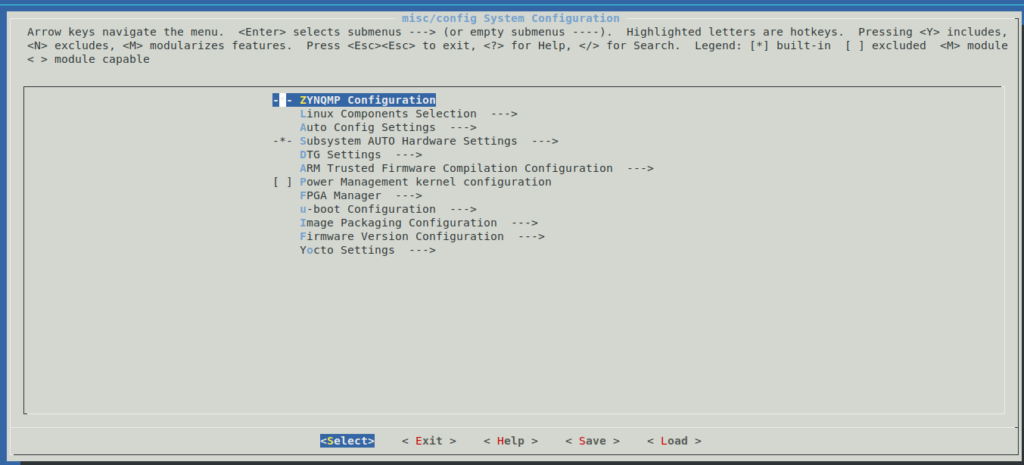
This menu will allow you to configure some of the higher level settings of petalinux such as serial/UART, ethernet, etc… I’d recommend leaving defaults with the exception of possibly the ethernet settings.
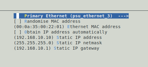
By default, your FZ3 board will be configured to obtain IP address automatically. There’s nothing wrong with this if you have it connected to a router or network that has a DHCP server, however, I directly connect my FZ3 board to my computer, so I need to assign a static IP. It’s also nice knowing what the address is. Once completed, save and exit the menu.
Because I haven’t introduced modules or libraries (yet), we can jump right into building:
user@computer$ petalinux-build
Building for the first time will take quite a while, but once finished, you should be able to try booting petalinux. Before doing so, ensure all jumpers for SW1 are set to ON (up). Note that on the silk screen, 0 = on, 1 = off.

This command will potentially be different for you depending on your programmer, the location and name of your generated bit file, etc.., but to program over jtag for booting petalinux, run the following command:
user@computer$ petalinux-boot --jtag --u-boot --kernel --fpga --bitstream ~/Projects/EdgeBoard_ZU3/EdgeBoard_ZU3.runs/impl_1/ps_module_wrapper.bit --hw_server-url 127.0.0.1:3121
It is worth noting that you may need to install cable drivers to support and work with the various Xilinx programming cables. To do this, run the following script (again, varying depending on where you installed Xilinx tools:
user@computer$ cd /tools/Xilinx/Vivado/2019.1/data/xicom/cable_drivers/lin64/install_script/install_drivers/
./install_drivers
The default baud rate is 115200 and if you have the USB cable connected to your FZ3 board, you should be able to see petalinux boot. At the end of the boot sequence you should see the ethernet link come ready:
user@computer$ PetaLinux 2019.1 plinux /dev/ttyPS0
plinux login: [ 13.024227] macb ff0e0000.ethernet eth0: link up (1000/Full)
[ 13.029913] IPv6: ADDRCONF(NETDEV_CHANGE): eth0: link becomes ready
Now it’s a matter of ssh’ing into your FZ3 board:
user@computer$ ssh [email protected]
The authenticity of host '192.168.10.10 (192.168.10.10)' can't be established.
RSA key fingerprint is SHA256:6X9ZnWpk8GCAjd+z6kcjyuWfpiJQn/TB34V+5B7EKls.
Are you sure you want to continue connecting (yes/no)?
Next: Custom AXI Block
My next walk-through related to this FPGA board will be demonstrating how to create a custom AXI Lite VHDL block in Vivado, and how to create a linux character device driver to interact with it. I hope this tutorial was helpful. Feel free to leave a comment or question below.


